How to program a AVR (arduino) with another arduino using atmega168 microcontroller

This instructables is usefull if:
* you’ve got your arduino with atmega168 and you bought an atmega328 at you local electronics store. It doesn’t have an arduino bootloader
* you want to make a project that doesn’t use arduino – just a regular AVR chip (like the USBTinyISP) – you have a clean attiny2313/attiny48 etc that you want to burn firmware on.
Normally  you would have to have an ISP (In System Programmer) like USBTinyISP to program your new chip.  Having the arduino you can teach it to be a programmer thank to a great work done by Randall Bohn. He created Mega-ISP – an arduino sketch that works like a programmer.

Step: 1 What do you need ?


* a working Arduino (or a clone – i’m using the BBB – BareBonesBoard and a RBBB – RealBareBonesBoard by ModernDevices)
* a chip that you want to program (tested with atmega8,atmega168,atmega368, attiny2313, attiny13)
* a breadboard or a board with ISP header
* 3 leds + 3 resistors
* breadboard wires

Step: 2 Making the mega-isp programmer on a breadboard


There are two ways to connect your Arduino to program a chip.
You can plug your avr chip to a breadboard and connect 5v and GND to the respective pins (check the datasheet!) + a pullup resistor to reset and wire pins from you arduino to the chip.
These are the lines on Arduino and their function
13 – SCK
12 – MISO
11 – MOSI
10 – RST (Reset)
Or you can make a 2x3pin ISP header that you can plug into a board that provides one (another arduino board).
The pinout for the ISP header is on the third image
There are 3 leds to indicate the status of the programmer.
pin 9 – blue led – its the hearbeat of the programmer.
pin 8 – red led – indicates an error
pin 7 – green led – indicates that the programming is taking place
(i was lazy so i didn’t match the colors in my setup)
Here are the drawings made in Fritzing
You can alsa make a MEGA-isp shield. Yaroslav Osadchyy designed the shield in eagle. You can get the eagle files on his site:  http://drug123.org.ua/mega-isp-shield/

Step: 3 Uploading the sketch

Download the sketch from mega-isp google code.(avrisp.03.zip at the time of writing).
Unpack it and run arduino ide and open avrisp.pde.
Upload it to your arduino board.
Heartbeat led should start beating.
For more detail, Click here...


Singing Pumpkins/ Arduino using microcontroller

Lets start off by saying that I am a noob to micro controllers like Arduino. After looking through instructables for a while I saw the things that arduino could do. That is when I realized that I had to get one and learn the whole process of programming. So having said that I will now move onto my first instructable build.
UPDATE!!   IF YOU HAVE UPGRADED TO ARDUINO 1.0 THE WAVE LIBRARY WILL NOT WORK!!! I AM CURRENTLY LOOKING FOR A FIX TO THIS. IN THE MEAN TIME PLEASE USE THE OLDER VERSION OF ARDUINO SOFTWARE OR IF YOU CAN HELP WITH THE FIX PLEASE POST!!
I decided to create a singing pumpkin display for Halloween. I got the idea from http://www.instructables.com/id/Singing-PumpkinsParallel-Port-Relay-Box/ I did’t have a parallel port but I had an arduino, sound shield and lots of patience. I used the song “This is Halloween” from Nightmare Before Christmas, wrote the code and built a relay board. I will go over how I did this later. Even though it took a lot of work the final result is well worth it! Video is posted in last step.

THIS PROJECT DEALS WITH HIGH VOLTAGE. IF YOU ARE NOT CAREFUL YOU COULD GET SERIOUSLY INJURED.
IF YOU ARE NOT COMFORTABLE WITH THAT PORTION OF THE PROJECT, PLEASE GET SOMEONE TO HELP.

Step: 1 Things you will need


Things you will need:
Tools:
Drill
Dremel
Solder Iron
Solder
Screwdriver
Utility Knife
Supplies:
Arduino ( I used the uno with smd chip)
Wave shield
8 pumpkins with light socket and cord( the more styles the better )
flicker bulb set ( available at HD Christmas isle)
5 outlets
relays
wire ( low voltage, electrical cord )
Preff board
9 diodes- Vr/50v Io/1A T/R. Mfg P/N: 1N4001
9 10k OHM 5% 1/4W carbon film resistors
9 330 OHM 1/6W carbon film resistors
9 transistors- 600mA 75V NPN ON Semi Bipolar Small Signal Mfg P/N; P2N2222AG
9 leds 3v
Plastic box ( for relay board and outlets )
Small plastic box ( protection for arduino and sound shield )
Masking Tape
Electrical tape
9v wall wart (adapter)
For the relay board set up I needed 9 relays that control 110v. That ‘s 8 for the pumpkins and 1 for the flicker bulbs that will run In standby mode. The relays I used are 5v input and 110v 12a output. The relays are wired to be controlled by the arduino but they are powered by a wall wart ( transistors are perfect for using a low voltage to control a higher voltage ). The circuit is simple( as you will see in upcoming steps). The arduino sends a signal to the 10k resistor which is connected to the center pin of the transistor. This will use the transistor as a switch to connect the negative from the wall wart to the relay pin by switching the ground.

Step: 2 Relay board 1

For this step I laid out my relays so I could get an Idea of how I wanted it to be. The relay I used had the load pin in the middle and it did not fit into the preff board so some drilling was needed ( see pic ). Now it’s time to place relays and solder them. Once the relays are all soldered we can now move on to placing the other parts. I started with the diode. Even though relays have no polarity the diode will change that ( diodes let the juice flow one direction ) and that will keep the voltage from bouncing back where it shouldn’t be.

Step: 3 Relay board 2


At this point I added the transistor and first resistor (10k). Since the transistor switched a ground or negative I placed it so the output pin is connected to the diode negative or ground side. ( side without stripe ). The resistor is connected to the signal pin of the transistor this pin is used to control the internal switch.
In the next picture I added the second resistor (330k). This is used to limit or resist the voltage to the led. In the picture it looks like it connects to the transistor but it is not. The side of the resistor that is facing away from the transistor will be soldered together.
By now the solder connections are as follows. Solder relay to the board. solder diode so that each pin is soldered to the relay signal pins. Place transistor and solder one pin to the negative side of the diode and relay. Solder the 10k resistor to the middle pin of the transistor. Solder the 330ohm resistor so that both resistors are connected opposite of that transistor.

Step: 4 Relay board 3

In this step add the led. Leds have a flat edge on one side this is the negative( – ) or cathode. This will be soldered to the last pin of the transistor. The other pin of the led the anode will be soldered to the 330k resistor. You may notice in the second picture the layout is slightly different then the first and that is because things got a bit tight for soldering. However the circuit remains the same. (See pic).
The next pic show the jumper wires used to connect the positive( + ). This will feed power to all relays with a wall wart. The jumper wires are soldered to the stripe end of each diode. It’s now a good time to add the signal wires. The wall wart negative (-) ground connects to the ground buss bar and arduino ground.
Now to the bottom of the relay board for some major work ( see pic ). I know the solder isn’t pretty but, hey,  it’s my first major solder project. Solder a buss bar to all load pins on the relays. Solder either a buss bar or jumper wires to all negative ( – ) connections. The negative connections need to connect to the ground on the arduino and to the negative on the wall wart. The only thing left to solder is the line wire from a male plug and the output load wires to each relay that will connect to your outlets.
For more detail, Click here...

Bluetooth Based Smart Home using atmega8 microcontroller

This project is used to automate the home appliances through Bluetooth enabled PC. You can use the USB Bluetooth at the PC side and an Serail Bluetooth converter is used at the microcontroller side. The sparkfun bluetooth module is used here, but you can use any serial bluetooth module which supports SPP profile. Atmega8 microcontroller is used in this project
The PC application software was written using visual basic and the microcontroller coding was done through Bascom Basic. The project had the following features
  • 2 Temperature sensor (1 Indoor & 1 Outdoor)
  • High resolution temperature sensors are used (0.06deg)
  • 1 Light sensor with help of LDR
  • 1 PIR motion sensor
  • 5 Devices can be controlled
  • LCD & LED interface to display the status

Post your doubts on the Forum

Circuit Diagram


PC Screenshot


For more detail, Click here...


Simple calculator using Atmega16 microcontroller

Here’s a simple calculator with the Atmega16 microcontroller. It have an LCD display and a 4×4 keypad.
You can also download the proteus simulation file on the downloads


Bascom Code


$regfile = “m16def.dat”
$crystal = 1000000
Config Kbd = Portd , Debounce = 30
Config Lcd = 16 * 2
Config Lcdpin = Pin , Db4 = Portb.4 , Db5 = Portb.5 , Db6 = Portb.6 , Db7 = Portb.7 , Rs = Portb.3 , E = Portb.2
Dim A As Byte
Dim B As Byte
Dim Key As Byte
Dim C As Byte
Dim D As Byte
Dim E As Byte
Dim F As Byte

Cls
Cursor Off
Locate 2 , 1
Lcd “avrprojects.info”
E = 0
B = 0
Q:
Waitms 200
‘B = 0
A = Getkbd()
If A > 15 Then
Goto Q
Else
Key = Lookup(a , Dta)
If Key <= 9 Then
D = 0
B = 10 * B
B = B + Key
If E = 0 Then C = B
If E = 1 Then D = B
Cls : Lcd B
Elseif Key = 10 Then
Cls
F = 1
E = 1
B = 0
Elseif Key = 11 Then
Cls
E = 1
F = 2
B = 0
Elseif Key = 12 Then
Cls
E = 1
F = 3
B = 0
Elseif Key = 15 Then
Cls
E = 1
F = 4
B = 0
Elseif Key = 13 Then
Cls
E = 0
B = 0
Elseif Key = 14 Then
If E = 1 Then
Cls
Select Case F
Case 1 :
B = C / D
Case 2:
B = C * D
Case 3:
B = C – D
Case 4:
B = C + D
End Select
Lcd B
End If
End If
End If
Locate 2 , 1
Lcd “avrprojects.info”
Goto Q
End
Dta:
Data 7 , 8 , 9 , 10 , 4 , 5 , 6 , 11 , 1 , 2 , 3 , 12 , 13 , 0 , 14 , 15
For more detail, Click here...

Measure negative temperature with Lm35

LM35 can measure temperatures from -55deg to 150deg and we need negative supply voltage for measuring this negative temperature.
This circuit eliminates the negative voltage power supply and this project can measure the negative temperature
Download the protesu file to simulate the project on your desktop


Bascom Code

$regfile = "m16def.dat"
$crystal = 1000000

Config Lcd = 16 * 2
Config Lcdpin = Pin , Db4 = Portd.4 , Db5 = Portd.5 , Db6 = Portd.6 ,
Db7 = Portd.7 , E = Portd.0 , Rs = Portd.1
Config Adc = Single , Prescaler = Auto , Reference = Internal

Deflcdchar 0 , 12 , 18 , 18 , 12 , 32 , 32 , 32 , 32
Deflcdchar 1 , 32 , 4 , 12 , 28 , 28 , 32 , 32 , 32
Deflcdchar 2 , 32 , 4 , 14 , 31 , 31 , 32 , 32 , 32
Deflcdchar 3 , 32 , 4 , 14 , 31 , 31 , 7 , 6 , 4
Deflcdchar 4 , 32 , 4 , 14 , 31 , 31 , 31 , 14 , 4
Deflcdchar 5 , 32 , 32 , 32 , 32 , 32 , 32 , 32 , 32

Dim A As Word
Dim B As Word
Dim C As Single
Dim D As Byte

D = 1
Start Adc

Cursor Off
Cls
Locate 2 , 1
Lcd "avrprojects.info"

Do

A = Getadc(3)
B = Getadc(4)
C = A - B
C = C / 4
Locate 1 , 1
Lcd "Temp =" ; C ; Chr(0) ; "c   "
Locate 1 , 16
Lcd Chr(d)
Waitms 500
Incr D
If D > 6 Then D = 1

Loop

End
For more detail, Click here...
DC Motor Speed Control using PWM

This project gives a speed control of DC motor through PWM method. The Dc motor is derived by the L298 driver IC.
You can also control the direction of the motor.
There are three buttons to control the motor. Also a bar graph Led display indicate the speed of the motor.
An proteus simulation file is also available at the download so that you can check the code on your PC.
Project from this Link


Bascom Code

$regfile = “m16def.dat”
$crystal = 1000000
‘============================================================================
Config Timer1 = Pwm , Pwm = 8 , Compare A Pwm = Clear Down , Prescale = 1024
Config Portb = Input
Config Portc = Output
Config Porta = Output
‘============================================================================
Dim A As Word , B As Bit
‘============================================================================
Declare Sub Progress(num As Word)
‘============================================================================
A = 100
Pwm1a = A
Portc.0 = 1
Portc.1 = 0
B = 0
‘============================================================================
Do
‘////////////////////////////////////////////////////////////////////////////
If Pinb.0 = 1 Then
A = A + 10
If A >= 250 Then A = 250
Pwm1a = A
Waitms 250
End If
‘////////////////////////////////////////////////////////////////////////////
If Pinb.1 = 1 Then
A = A – 10
If A <= 10 Then A = 10
Pwm1a = A
Waitms 250
End If
‘////////////////////////////////////////////////////////////////////////////
If Pinb.2 = 1 Then

If B = 0 Then
B = 1
Portc.0 = 0
Portc.1 = 1
Elseif B = 1 Then
B = 0
Portc.0 = 1
Portc.1 = 0
End If
Waitms 250
End If
‘////////////////////////////////////////////////////////////////////////////
Call Progress(a)
‘////////////////////////////////////////////////////////////////////////////
Loop
‘============================================================================
End
‘/\/\/\/\/\/\/\/\/\/\/\/\/\/\/\/\/\/\/\/\/\/\/\/\/\/\/\/\/\/\/\/\/\/\/\/\/\/\
Sub Progress(num As Word)
If Num < 25 Then
Portc.7 = 1
Portc.6 = 0
Porta = 0
End If
If Num < 50 And Num >= 25 Then
Portc.6 = 1
Portc.7 = 1
Porta = 0
End If
If Num < 75 And Num >= 50 Then
Portc.6 = 1
Portc.7 = 1
Porta = &B00000001
End If
If Num < 100 And Num >= 75 Then
Portc.6 = 1
Portc.7 = 1
Porta = &B00000011
End If
If Num < 125 And Num >= 100 Then
Portc.6 = 1
Portc.7 = 1
Porta = &B00000111
End If
If Num < 150 And Num >= 125 Then
Portc.6 = 1
Portc.7 = 1
Porta = &B00001111
End If
If Num < 175 And Num >= 150 Then
Portc.6 = 1
Portc.7 = 1
Porta = &B00011111
End If
If Num < 200 And Num >= 175 Then
Portc.6 = 1
Portc.7 = 1
Porta = &B00111111
End If
If Num < 225 And Num >= 200 Then
Portc.6 = 1
Portc.7 = 1
Porta = &B01111111
End If
If Num < 255 And Num >= 225 Then
Portc.6 = 1
Portc.7 = 1
Porta = &B11111111
End If

End Sub
For more detail, Click here...

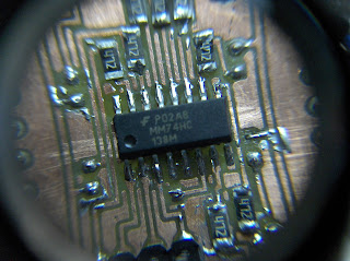
8×8 Bicolor LED Matrix using MAX6964

For a long time I had a layout for this circuit, but could never build it, because the layout was to small to be made by tonertransfer.
So it was the first layout I made with my new exposure unit. It’s quite small, so it fits under the LEDMatrix itself. Therefore only SMD parts are used.
It took three trys to get it right. The first failed because the etching solution was to weak, took to long and caused heavy underetching. The second was not properly exposed.

The third try worked perfectly. The alignment of the two layers was good and the etching took only 10 minutes.
Soldering the SMD resistors and transistors was not very difficult using a magnifyer and tweezers.
The 74HCT138 was more or less easy to solder, but the MAX6964 was a bit harder. (The pins have a pitch of only 0.635mm.) But with desoldering braid any superfluous solder can be removed.
The MAX6964 is controlled via I²C. It has 2 8-bit registers which switch the 16 outputs on and off and 8 8-bit registers which controll the brightness (via PWM).
To keep the layout easy and the number of vias low, i had to wire the pixels of the LED matrix in somewhat weird way. But this is easily compensated in software.


The correct order for the rows is saved in a lookup-table (just an array).
The data for one row is two bytes long. The first byte contains the data for the first four pixels. (Two bits per pixel, for red and green.) The first byte is left to right, the second byte is right to left.
Most of the code is I²C communication and transforming pixel data to the correct format for the MAX6964.
Layout and code can be downloaded here. Datasheet for MAX6964 here. (Maxim is very generous when it comes to shipping free samples.
For more detail, Click here...

EPROM Display using ULN2308A microcontroller

Due to university and work it has been a while since the last post. But I just completed a little project that’s worth posting.
Several old 27C256 EPROMS were lying around unused. So I thought about a purpose for them. As I also had some 8×8 LED matrices, a little animated display came to mind.

With each frame consisting of 8×8 pixels the 32kByte EPROM can hold 4096 frames. Each byte holds one line of the display, eight bytes one frame.
The lower 3 addressbits of the EPROM have to by switched synchronously with the corresponding line on the display. This is achieved by wiring them to a 3-to-8-decoder (74*238) which in turn switches the lines. As up to eight LEDs can light up at once per line. To handle the current an ULN2308A darlington driver is used.


The columns are directly controlled by the data-output of the EPROM. To drive the LEDs a 2N2907 transistor is used.
The clock is generated by a crystal oscillator circuit consisting of a 32768 Hz crystal and an inverter gate.
The 32kHz squarewave from the oscillator is then divided by a 12-stage ripple counter (4040). The seventh to ninth stage are used for the line-addressing and are wired to the A0-A2 inputs of the EPROM and to the A,B,C inputs of the 74*238.


The next three stages are connected to a DIP-switch. The output of the switch leads to the clock input of another 4040. This way the frame-rate is selectable from 32fps, 16fps and 8fps.
Only fourteen addresspins of the EPROM are used, the fifteenth can be set to high or low via a jumper.
For more detail, Click here...

CNC Update 2 Using atmega32 microcontroller

Another update on the CNC.
The interfaceboards are etched, soldered and tested.


IO / Control Boards
Step- and directionsignals are generated by an ATmega32 which is controlled over RS232.
This is only for testing purpose. In the final version a PC will control the movement.
For more detail, Click here...

Delta Robot using atmega32 micrcontroller


And now for something completely different: A little robotics project for the weekend.
The described robot can be build entirely from model making supplies and materials from the hardware store.
Also only very few tools are needed. A metal saw, a drill press, a vice and optionally a tap will suffice.
From the model making store you need:
  • 3 Servos  with M3 thread in the axis  (e.g. HX12K)
  • 12 ball joints with M3 threads and 3mm holes in the sphere (e.g.  Kavan Maxi Ball links 1405)
  • about 4grams of Polycaprolactone (Sold under names like ShapeLock or Friendly Plastic)
Form the hardware store you need:
  • 850mm of M3 threaded rod (sometimes also available for model making)
  • 27 M3 screw nuts
  • 3 M3 screws 5mm long
  • 3 M3 screws 15mm long
  • 400 mm of 10mm square hollow aluminum profile (1mm wall thickness)
  • 150×150mm metal oder wooden plate for mounting
(To control the robot you need a microcontroller of your choice.)
The first step is to divide the aluminium profile in three pieces of 100mm length and three pieces of 30mm length.
Then 4 holes are drilled and tapped in each of the pieces according to the following drawings.


One timer is used to generate an interrupt every 20ms / number_of_servos. On each of those interrupts one servosignal is switched on and a second timer is started. This timer is set to overflow after 1-2ms according to the desired position of the servo. When the overflow interrupt of the second timer occurs, all servosignals are switched off. This way you do not a variable to save the current servo, because only one servos is active at a time anyway. On the next interrupt of the first timer the process repeats with the next servo. The desired positions can be saved in an array.


With this method up to 10 servos can be controlled with only two timers and very short interrupt service routines. This way there is much remaining processing power left for other calculations such as receiving and decoding commands via the UART or I²C. Maybe you can even fit the inverse kinematics into the µC.
For more detail, Click here...

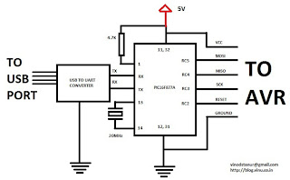
My own AVR ISP programmer using PIC16f877a

Introduction:
(don’t skip to read the note below)
I recently purchased few AVR microcontrollers. I don’t know much about AVR since I am using it for first time. Any way, I have some experience on working with PIC and MSP430. To program AVR using USB, I came to know that USBASP is the best and cheap choice. But any way, I thought of making my own ISP programmer (both PC software and burning hardware) for AVR using my fav PIC (PIC16f877A) microcontroller just for getting familiarised with the process of loading the binary into the AVR flash.


From PC side, coding is done on python. In short words, the python script reads the hex file (intel hex format) and make some ascii conversion on it and then send it to the PIC16F877A line by line. Now by using some commands for isp programming, the PIC communicate with AVR and transfer the data to it via SPI. I have tested my programmer on atmega8, atmega16 and atmega32.
Note:
I did this just for learning some thing about the burning process, please don’t consider this seriously because this may have many bugs , I don’t know and I didn’t tested much. Also I am not interested to continue this because it will be time wasting as there are already many cheap and efficient avr programmers available now. So please don’t complain about bugs and don’t use this for any important purpose.
For more detail, Click here...
TV remote controller 160KHz High Quality Stereo MMC WAV player using ATMEGA32

Introduction:
This is my first AVR based hobby project and the most successful one compared to my all previous stuff. I am 100% satisfied with this work. Few months ago, I tried to make a wav player using a PIC16F877A. It worked anyway, but the audio quality was not so good for higher sampling rate because that chip doens’t have enough ram and thus I couldn’t implement a good data buffer. But when I bought an atmega32 microcontroller, the first thing came to my mind is to make a good wav player…Now, I have completed my work and the audio quality is really amazing…  NOW I can say that, my wav player IS ABLE TO PLAY 8 BIT MONO/STEREO with maximum bitrate of 1300kbps for mono and 1600kbps for stereo … ie it can play an 8 bit mono wav of sampling frequency upto 160KHz and stereo upto 96KHz  without any noise or trouble!!!!! (at OSC 16.450MHz).


Note:
[The full range of human hearing is between 20 Hz and 20 kHz. The minimum sampling rate that satisfies the sampling theorem for this full bandwidth is 40 kHz. The 44.1 kHz sampling rate used for Compact Disc was chosen for this and other technical reasons.   High-end audio equipment, such as in SACD or DVD-Audio players or studio equipment, can reach as high as 192 kHz.]
        Now I believe this is a perfect 8 bit stereo wav player. Because I compared the same converted files played in my PC and in my player, but I couldn’t find any difference in the playback quality. You can see it on the video (it is taken through my mobile phone, so the recorded audio may not be as good as the real one). Any way,  since the PWM have some limitations, I also tried the R2R ladder DAC… But I couldn’t find any more improvement because it is already at it’s top quality. Also, I think since I converted MP3 to WAV, so even if I increase the sampling rate in the conversion process, just for testing the maximum capacity of the player, but that couldn’t help me to find the difference of PWM and R2R because the original audio is having a sampling rate of only 44.1KHz… So I am not going for an R2R dac and instead I am using the PWM itself…
 
Another interesting feature of my player is that, it could be controlled with a Philips TV remote (RC5 protocol). Also I had implemented few functions on the remote control, ie NEXT SONG, PREVIOUS SONG,  PAUSE, PLAY, FORWARD 15 SECONDS, and some funny effects like PLAY SPEED INCREMENT and DECREMENT. Also I am still trying to include more features on the remote… The player is now a beta_version …. Also, I didn’t used any external FAT libraries for the low level MMC accessing, instead I had written my own code for that… So you may not be able to find any standard ‘C’ FILE operations on my source code.

Multitasking in AVR using atmega32 microcontroller

Introduction:
     Switching multiple tasks on a same CPU is the one of the major function of an operating system. What I did now is a time sharing multitasking (time multiplexing) on an AVR. Here an atmega32 is configured to use Round-Robin Multitasking. Round-Robin allows quasi-parallel execution of several tasks. Tasks are not really executed concurrently but are time-sliced (the available CPU time is divided into time slices).
         Here, in my code below, it consist of 7 independent tasks and those are switched from one to another on a timer interrupt. ‘May be’ this could be considered as a simple & very basic RTOS demo…
Scheduling algorithm used: Round-robin (RR)


Working: 
 Here, total RAM (2KB) is divided among 7 tasks almost equally in such a way that each one get around 300 bytes of RAM space. This 300 bytes is considered
as the stack for each task. When the timer reaches the compare value, it trigger an interrupt. Now inside ISR, at first all the registers are pushed onto it’s stack. Program counter is already push (automatically) at first when the interrupt is triggered. Now after pushing all the registers, the status register is pushed onto the stack(avr doesn’t do it automatically). Thus we made a backup of all the register values and the status register and we are safe to use those register for some other purpose. Now the next process is the switching between tasks ie the context switching. Before that we need to backup the current stack pointer otherwise we will miss it and couldn’t resume the task when it’s time slot appears for the next time. So a 50(more than enough) bytes are reserved from the RAMEND to store the task index(which task is running now) and the stack pointers of all the tasks. This is considered as the stack pointer backup table or array.
       Now, when the task1 is interrupted by the switching timer interrupt, as said above, it push all CPU registers and the status register. Then it checks the ‘task index’ which will be there on the RAMEND. From the task index, we get the task number and thus we can obtain the exact location on the stack backup table on which the stack pointer value is to be stored. Also we can get the next task’s stack pointer value relative to the location where we stored the current one and that is loaded to the stack pointer. So, we got the stack pointer of the next task. Now, we can pop the status register and all the cpu registers and finally the RETI instruction will enable the global interrupt and then divert (jump to new PC value) the cpu to resume the next task…. This repeats with a time slot in range of micro seconds and thus we feel all the tasks are running in parallel and also purely independent even though they are using the same cpu registers in common. Here are some pictures which I drawn to make the above explanation more clear. It represent the RAM usage for the stack pointer backup table and the process stack.
For more detail, Click here...

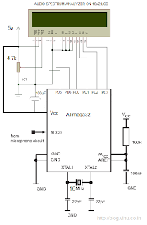
Implementing Discrete Fourier Transform in Atmega32 to make an audio spectrum analyzer

“All waveforms, no matter what you scribble or observe in the universe, are actually just the sum of simple sinusoids of different frequencies.”
Hi,
I am just refreshing the basics of fourier transform. I am not an expert. Now I did a small audio spectrum analyzer(0 – 10KHz) on a 16×2 character lcd using an atmega32 microcontroller. Since I am refreshing from the basics, so I started with simple DFT. Also, I believe I should learn to walk before running. So I am not straight away going towards the FFT, which is nothing but the fastest and a bit complicated algorithm to find DFT.(I will try it later, as soon as possible)
 
DFT is too slow compared to FFT. My lcd spectum analyzer doesn’t need a great speed like that of an FFT, now if it is capable of providing a speed of around 30 frame/second, then it is more than enough for visualizing the audio spectrum on an LCD. But any way, in my case I can roughly achieve around 100 frames/second(any way it is too high refresh rate for a 16×2 lcd, not recommended also icon smile Implementing Discrete Fourier Transform in Atmega32 to make an audio spectrum analyzer ). My audio sampling rate is 20KHz for 32 point DFT. Since the transform result is symmetric, I need to use only the first half, ie the first 16 results. So, it means, it can display upto 10KHz spectrum. So the resolution is 10KHz/16 = 625Hz.
         I have tried to improve the speed of DFT computation. If it is an N point DFT, it needs to find (N^2)/2 sin and cos values. For a 32 point DFT, it needs to find 512 sine and cosine. Before finding the sine and cosine, we need to find the angle(degree) which takes some processor time, so I implemented a lookup table for that. Next two tables are for sine and cosine. I didn’t used any float or double since it takes more processing time in 8 bit avr, instead I implemented the sine and cosine lookups as 16bit intiger, by multiplying the real sine and cosine values by 10000. Then after finding the transform, finally I need to divide each result by 10000. This eliminates the need of using float or double and makes it more faster. Now I can calculate 120  32-point DFT operation/sec which is more than enough for my small spectrum analyzer.
 
LCD
       Now, looking towards the LCD side, I utilized the custom character feature of LCD to make 8 stacked horizontal bars which takes the entire 64bytes of the LCD RAM for custom character bitmap. I ones seen a video is hackaday.com that a person used a 16×2 lcd in the similar manner for his spectrum analyser. So I also adopted the same idea of using the custom character for my spectrometer.
AUDIO INPUT
       Now one of the most important part of this stuff is the audio sampling via an eletret microphone. Special care must be given while designing the pre-amp for the mic. We need to set the zero-level of the ADC input to exactly half of the ADC reference voltage ie to 2.5v. Now it can have positive and negative swing on this 2.5v level according to the input audio signal but it should not cross the limit ie the amplifier gain should be properly adjusted to prevent clipping. I am using an LM324 op-amp for the mic pre-amp to meet the above conditions.
 

An attempt to show grayscale images on an LED dot matrix display with software PWM using PIC16F877A

Introduction:
This is just a time pass hobby project, I am trying to display some pictures (JPEG/PNG/BMP etc) on my 8×8 led dotmatrix display.  You can see photos of my 8×8 led dotmatrix display showing some grayscale pictures. The main thing which you may notice is that the brightness of each led depends on the picture information respective to the scaled(8×8) pixel of the original picture.The original pictures are drawn using GIMP image editor in linux and saved as png. The scaled pictue is sent from the PC to PIC via UART.
Any way, this will be the worst monochrome display showing pictures:


Photos: 
Here you could see the led display showing few pictures opened in gimp editor… You could compare the pictures and observe the PWM effect on the led matrix.
Working:
A pic16f877a is the heart of the 8×8 display. It is configured to drive the matrix. Brightness of each led is controlled by software PWM. A 64 byte buffer(in pic) is used to store the brigntness information of 64 leds. Also another 64byte buffer is used to collect data(picture information) streamed out from PC via UART. Now, from PC side, every thing is done using a python script. Python image library (PIL) is used to convert any picture to 8×8  grayscale image. Now we get 64 bytes of data from a converted picture. Each byte value is divided by 4(since value 64 is the pwm max) and introduced to the PIC via UART using pyserial. When the 64 byte packet is completely received, it is introduced to the display. It show a single frame for about one second. Then next 64byte is sent from the PC and it is displayed and it continues.
For more detail, Click here...

AVR based monochrome signal generation for a PAL TV using atmega16 micrcontroller

Introduction:
I have learned some thing about TV in one of my B.tech semester but I forgot most of them. Now I refreshed a few basics and tried to implement a monochrome PAL TV signal generator using an AVR micrcontroller. I was using PIC earlier but later I jumped to AVR because I loves the USBASP programmer, the free avr-gcc compiler and the user friendly architecture of AVR microcontroller .Also at any time, if I feel little bit lazy, they I can try arduino also.


At first, my aim was to display few A B C D letters on my tv screen. But it is not possible for a beginner to do it directly(at least in my case) without doing any hello world stuff on TV. The first and the basic hello world pattern which one could display very easily on his tv is a vertical line of desired thickness and position. This is very easy because we don’t need to provide any vertical synchronization to lock the picture scrolling on vertical axis, what we need to provide is a horizontal synchronization only.
Synchronization:
  We need to display a picture exactly on it’s position relative to the coordinates of the tv display. ie we need to lock a picture frame on the screen and it should not vibrate or move up and down or it should not disturb the scanning rules. For this along with the analog picture data (.3 to 1v), we send few digital data of 0 – 0.3 v levels which do the synchronization process. There are two synchronizations , the horizontal synchronization and the vertical synchronization.
   Horizontal synchronization pulse in the signal makes it synchronized with the horizontal scanning. Similarly vertical synchronization pulses(a stream) makes it synchronized in the vertical direction , this ensures that the picture always starts from the top on each field(each interlacing fields) and locks the picture on the screen on it’s exact position. Vertical synchronization is a long compared to horizontal synchronization.
For more detail, Click here...
Drawing geometric figures on a PAL TV using ATmega32 microcontroller

Introduction:
I am interested to draw lines, square, rectangle, circle etc on my TV screen. At first I was confused where to start. While thinking about it, a pencil and an eraser came to my mind. If we have a good pencil, eraser and a paper, then we can draw on it according to our own logic. If we use the pencil with compass and scale, we can draw circle, line, box etc on the paper. This is the basic idea I implemented in this small hobby project.


I divided my tv screen into 128 x 64 pixels. I am using atmega32 microcontroller. It got 2kb RAM. So, if each pixel takes 1 bit, then 128 x 64 pixels takes (128*64/8) = 1024bits of RAM(screen buffer). Still I can increase the resolution but any way at present I am satisfied with this because it is my first attempt and I can improve it later.
Here a horizontal line in TV(two lines) takes 16byte, ie horizontal resolution now is 16*8 = 128 pixel. Similar 64 bytes are stacked up and thus the vertical resolution now is 64 lines. I am using fake interlacing so total vertical lines are 312 and here again I combine 2 lines to a single line which takes 1 16byte row of the screen buffer.
          I told about a pencil at the starting of the post, that is nothing but a function which could set a pixel. The eraser is a function which clear a pixel. Now the paper is the a digital display of 128×64 pixels, the smallest dot is 1 pixel.
 
PENCIL =  setpixel(x,y);
ERASER = clrpixel(x,y);
PAPER = 128×64 screen
building block = one pixel
Now my first aim is to create the pencil and eraser so that I can draw any thing on my TV screen using simple mathematics….
I am setting a character array disp_buffer[64][16] ie 1024 bits (128×64) which stores each pixel information and we will be playing on this buffer to draw pictures.
A brief explanation about the working of TV is provided at my previous post.. Ok, now before going to the pencil, we need to set the paper. Here we need to set the display buffer to show it on TV. May be this will be one of the most important part of the code. A raster scanning of a TV takes 64uS. So we need to generate timer interrupts on each 64us and we need to use more precise and peak value clock, the external crystal of 16MHz. But unfortunately, I don’t have a 16MHz but have a 16.450MHz. So I stick with it and all of my code will be related to that. I will update it soon when I get a 16MHz.  We can easily calculate the timer compare value to be loaded into OCCR1A using below equation. For more detail, Click here...

Running PYTHON (pymite-09) on an Arduino MEGA 2560 using atmega16 micrcontroller

Now it is the first time I am using an arduino board. Arduino mega 2560 is really a great product. The chip got a flash of 256KB, RAM of 8KB and EEPROM of 4KB. Also, the data sheet of Atmega2560 says that we can extend the RAM (by external) upto 64KB. Another most important feature of this stuff is that it have 54 Digital I/O pins (of which 14 provide PWM output). It is clocked with a 16MHz crystal osc.


Also the board contains another atmega16 (just above the crystal) which is pre-programmed as a USB to UART converter which enables a serial communitation between the atmega2560 and  PC via USB. The product is shipped with a bootloader inside which make it easy to program it via the same USB-UART channel. So the channel got two functions, ie programming the chip and serial communication with PC. From the arduino home page we can download the arduino IDE for appropriate OS.

      I heard arduino makes people lazy. But now I understood it is true. Because it is so easy to program an arduino using the arduino IDE. It have an arduino language (it is c++) with a great library functions those are very much user friendly and I heard people saying, “if it is arduino, any one can program it”. Now I believe statement is almost right because in arduino IDE, we doesn’t need to know any thing about the processor, it’s registers and even its real port address also. Every thing is grouped and numbered in the board not according to the real PORTA, PORTB etc but according to it’s functioning like PWM, ANALOG, DIGITAL, COMMUNICATION etc.
The arduino IDE got a lot of working examples, what we need to do is, we need to select the board first and then set the serial port and later we can open any example and then simply press ‘upload’. It is ready!!!
So no need to explain it more because it is so simple.
For more detail, Click here...

Generating AUDIO ECHO using Atmega32 microcontroller

Introduction:
But now I can do this very easily by a simple digital signal processing using a microcontroller. It’s concept is very simple, ie we need to apply a proper delayed feedback in digital samples with in a circular buffer. I did this using an atmega32 microcontroller and it worked fine. This is simple but really an interesting project. Not only an echo, but we can do a lot of fun with this type of small DSP experiments if we have considerably large RAM in the mcu…


Working:
 I am using an Atmega32 microcontroller for the purpose. It is having RAM of 2KB and an ADC which is enough for demonstrating the concept of echo generation. An electert mic is used for capturing the voice. It is introduced to ADC with proper amplification and level shifting, which are more critical for the perfect operation.

Now the ADC module inside the AVR will convert the analog signal to digital signal at a particular sampling rate(which we can decide).  Now a 1900byte circular buffer is introduced. Our first aim is to make a delay in input and output audio. So, we can do one thing, ie we can populate the buffer from one end and we can read the buffer from another point so that there will be a delay! So how to make this delay to it’s maximum? I think it will be better to explain it via a diagram. 
For more detail, Click here...